The circuit described in the "patent" does not work correctly. Fixing the diode to a constant potential, or begins the "grid current limiting" almost immediately (at small signal levels) or gives to transistor a possibility fall in saturation at high levels (depending on the fixing potential).
Many thanks to Mikhail Semenov (OldMike) for the idea of "scalable diode"
On this basis, has developed the following schematics of the basic stage.
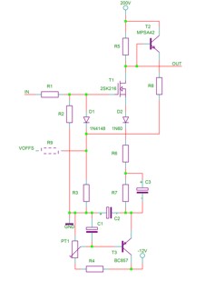
Resistance of resistors R6, R7 determine the gain of the stage below the cutoff frequency, and the resistance of the resistor R6 above the cutoff frequency. Chain D1, T2, R8, R3, (possibly R9) forms the "scalable diode". By selecting the parameters of components we can accurately determine the position and shape "of the grid current limitations."
Schematics of test equipment.

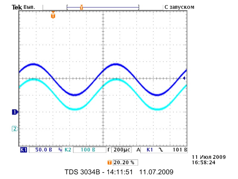
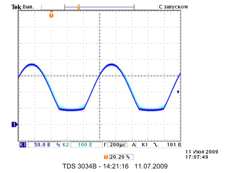
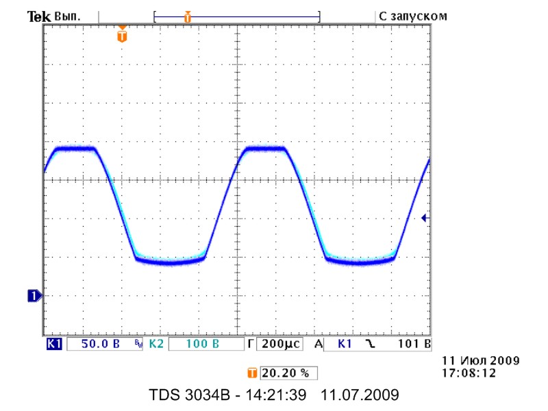
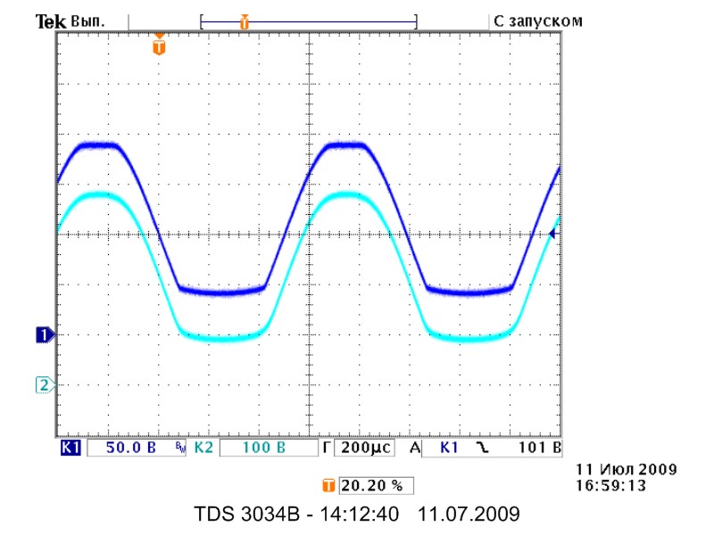
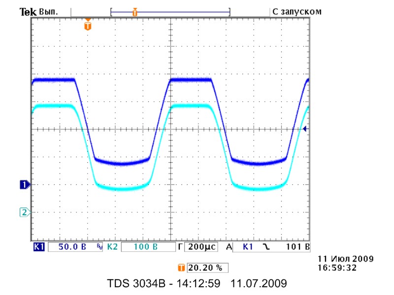
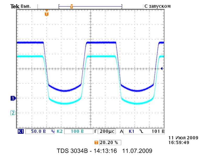
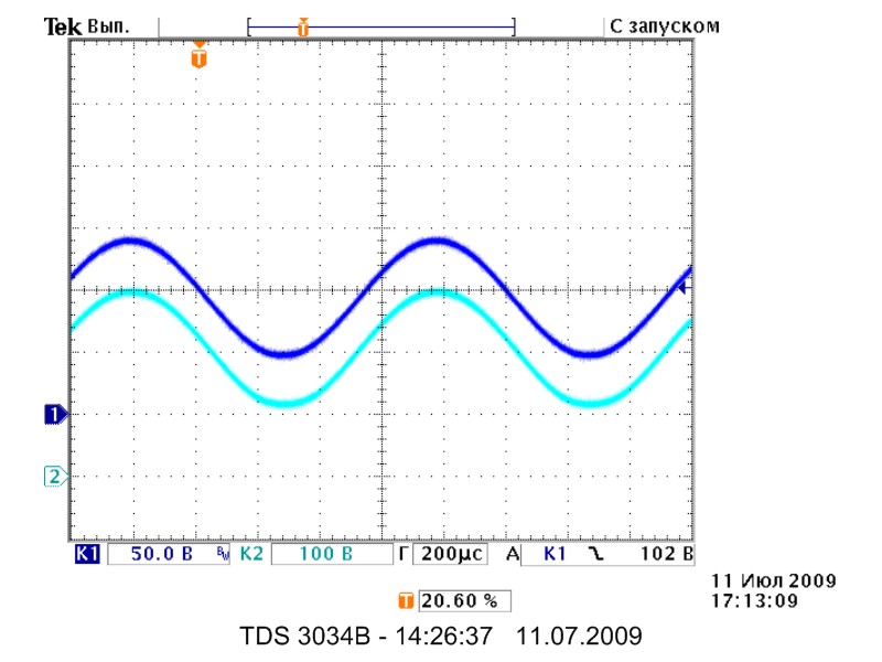
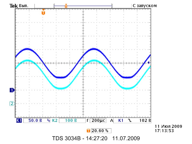
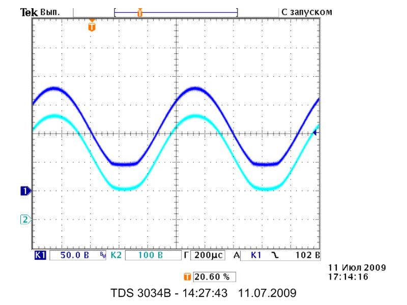
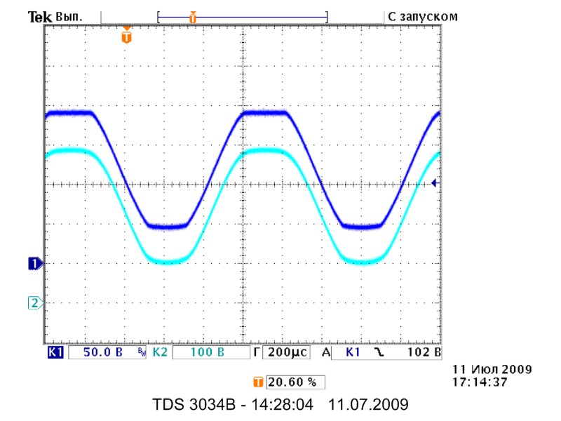
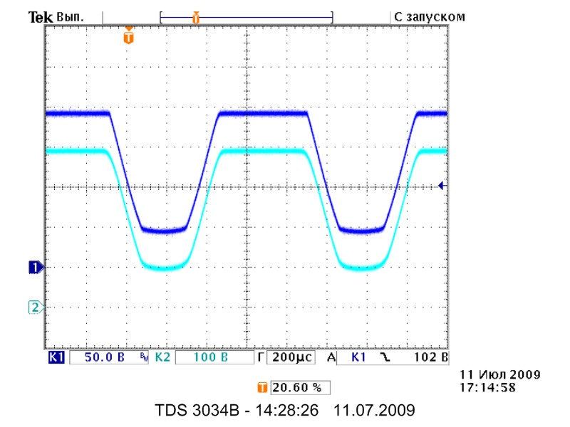
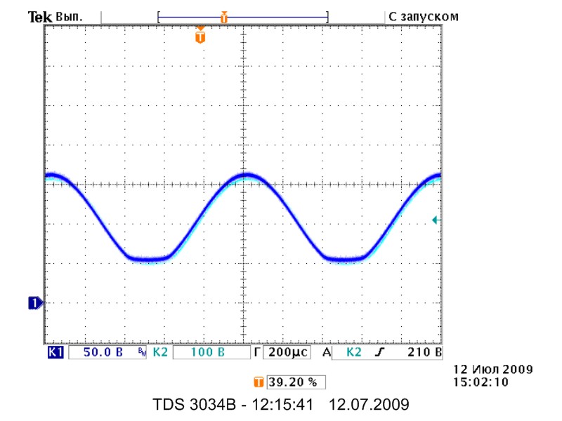
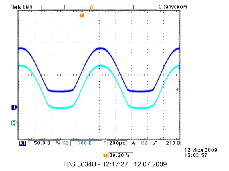
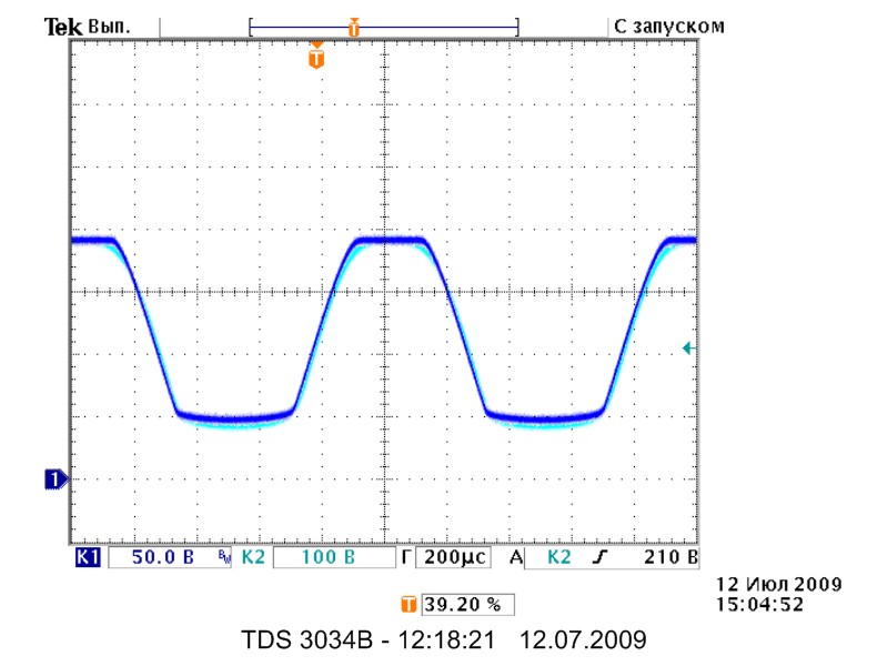
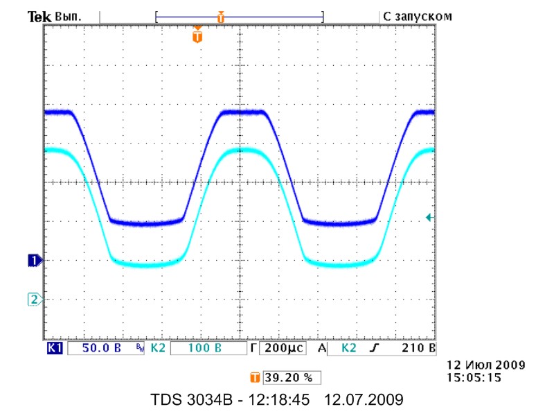
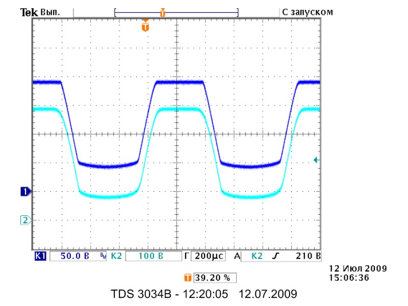
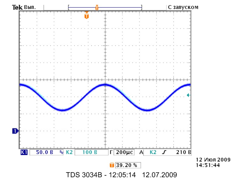
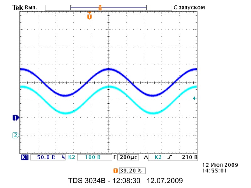
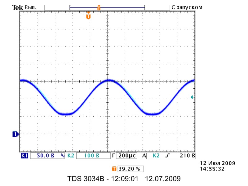
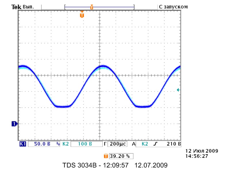
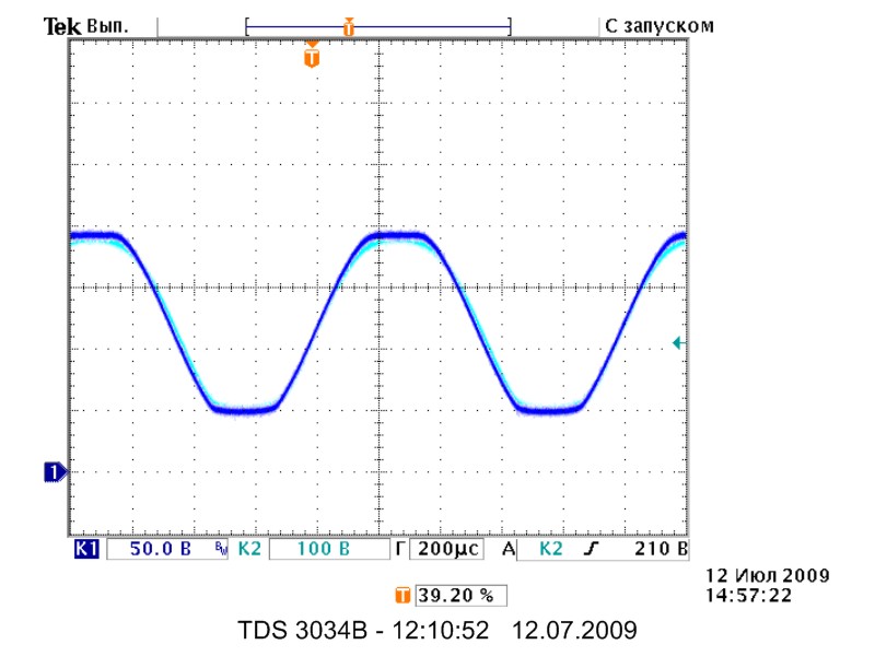
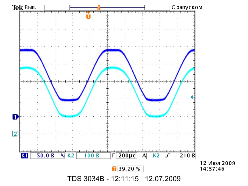
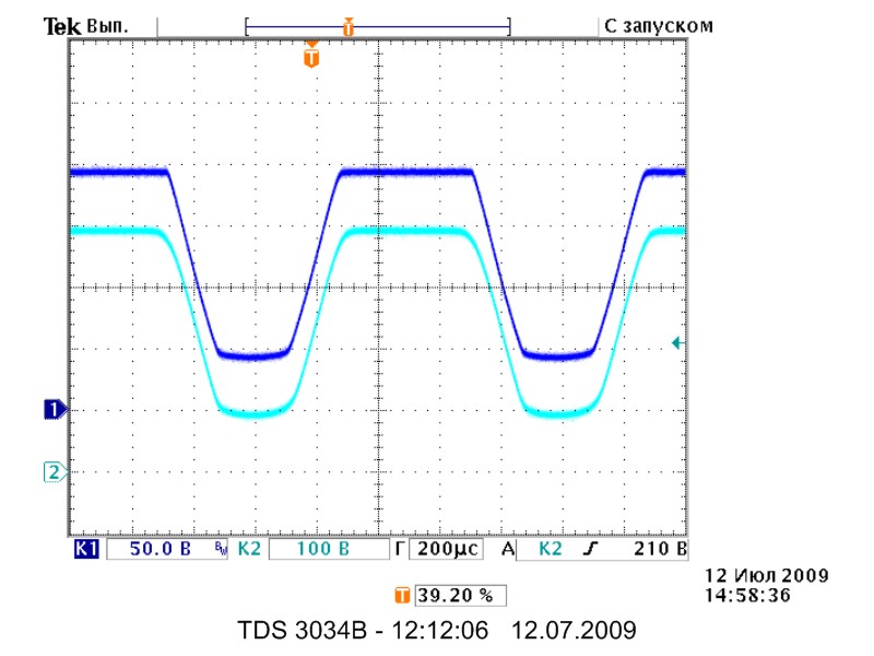
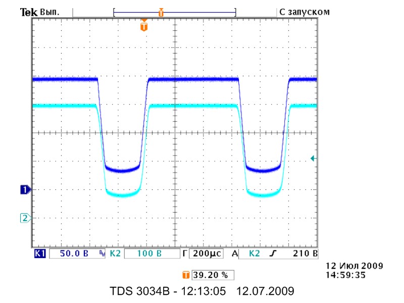
Dark blue color shows the output of mosfet stage, light blue - the output of tube stage.
Right waveforms are shifted vertically by the cell relative to each other, to better show the difference.
Without the boost - SW2A, SW2B and SW2C Off.
DC input coupling - SW1A and SW1B On.
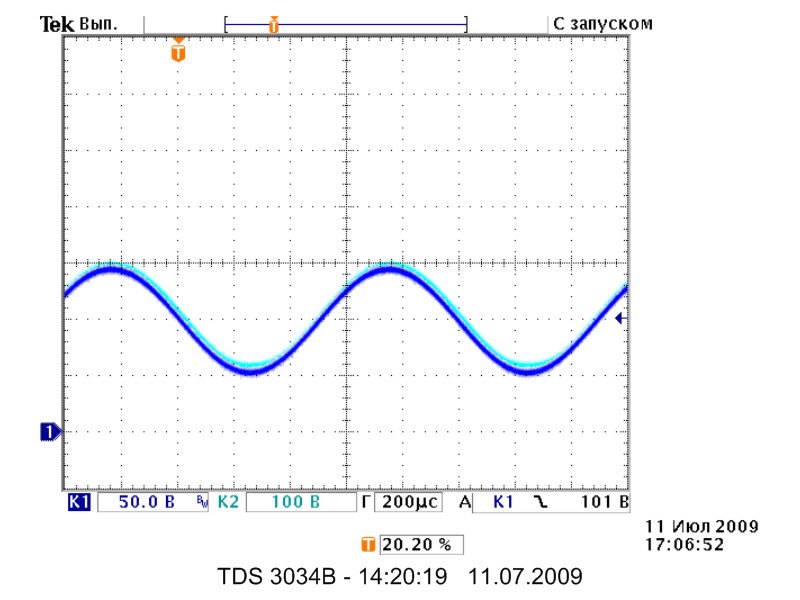


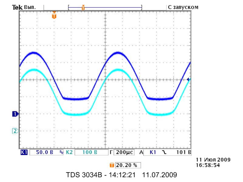

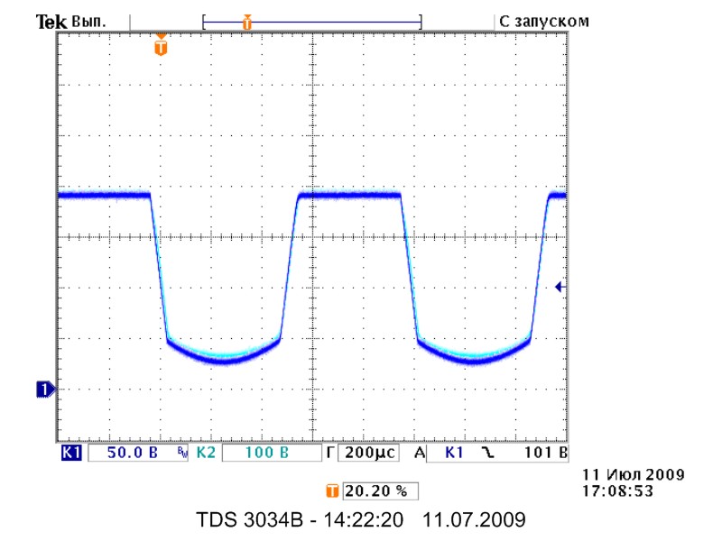
There is a noticeable difference in the form of limitation on the upper half wave, it can be minimized by increasing the number of germanium diodes in the source of mosfet (with 5 diodes form becomes indistinguishable from the tube)..
AC input coupling - SW1A and SW1B Off.


Fixing constant component to the decoupling capacitor by the grid and "grid" current is analogous to both circuits.
With the boost - SW2A, SW2B and SW2C On.
DC input coupling - SW1A and SW1B On.


AC input coupling - SW1A and SW1B Off.


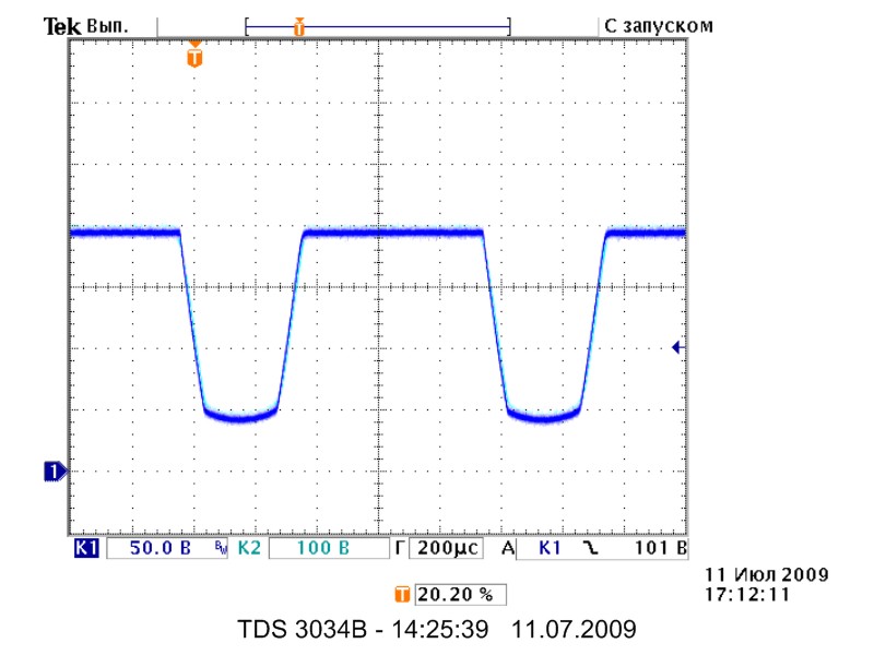
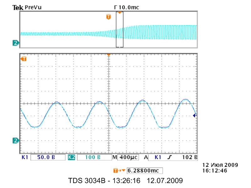
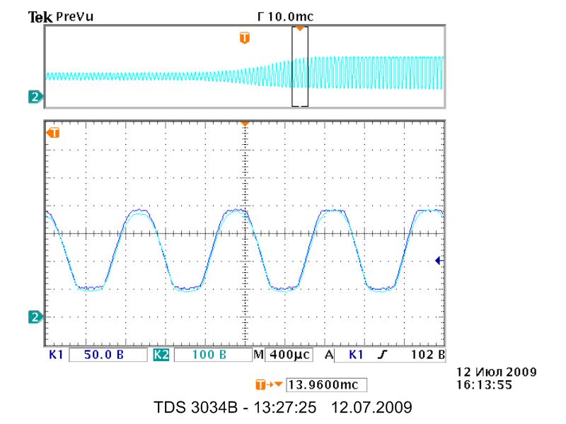
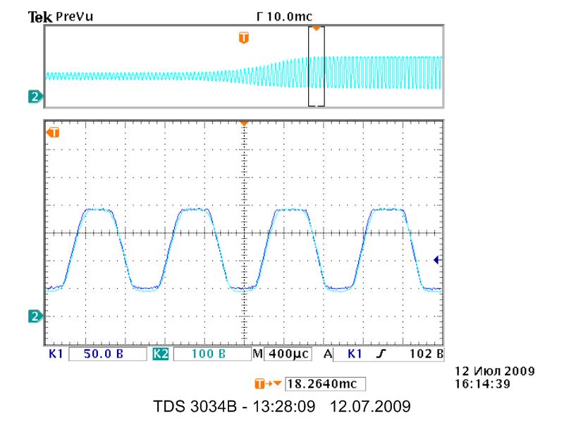
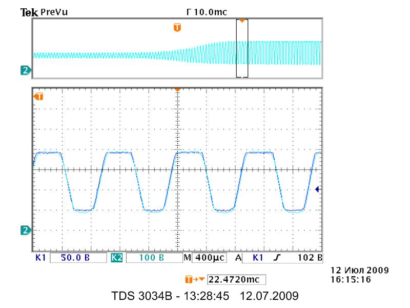
Response to a sharp increase in the input signal.


Some words about the effect of Miller. Most of all he had seen on stages with high gain, especially without local negative feedback (with a capacitor in the cathode circuit).
Comparative AFC tube and FET. Comparison was performed on stage - 1MOm on the ground, 470kOm in series with the grid, 1.8 kOhm + 1uF in the cathode, and 100 KOhm at anode.

FET stage begins to cut response later and less sharp.
If you add a 100pF capacitor from the FET gate on the ground, then the response leveled with tube stage.