Fet power amplifier with transformer output
In the proposed versions of the amplifiers used JFETs or lateral mosfets because they have the transfer and output characteristics almost identical to pentodes that allows as close to a tube sound. They also have a negative drain current dependence on temperature, which eliminates the need for thermal stabilization (Avoid to use vertical mosfets such as IRF, they works properly for sound only as source followers and also has positive drain current dependence on temperature). The amplifier is built on the classic "tube" schematics - differential stage and further push-pull output stage that drives the output transformer. Transformer allows you to achieve two objectives - protection of the speakers at a failure of output transistors and matching with different impedance speakers (using the taps of the secondary winding)
250 мW, ideally for "night" playing
Schematics (pdf)
Ready to transfer PCB (pdf)

Upper side assembly (pdf)

Bottom side assembly (pdf)


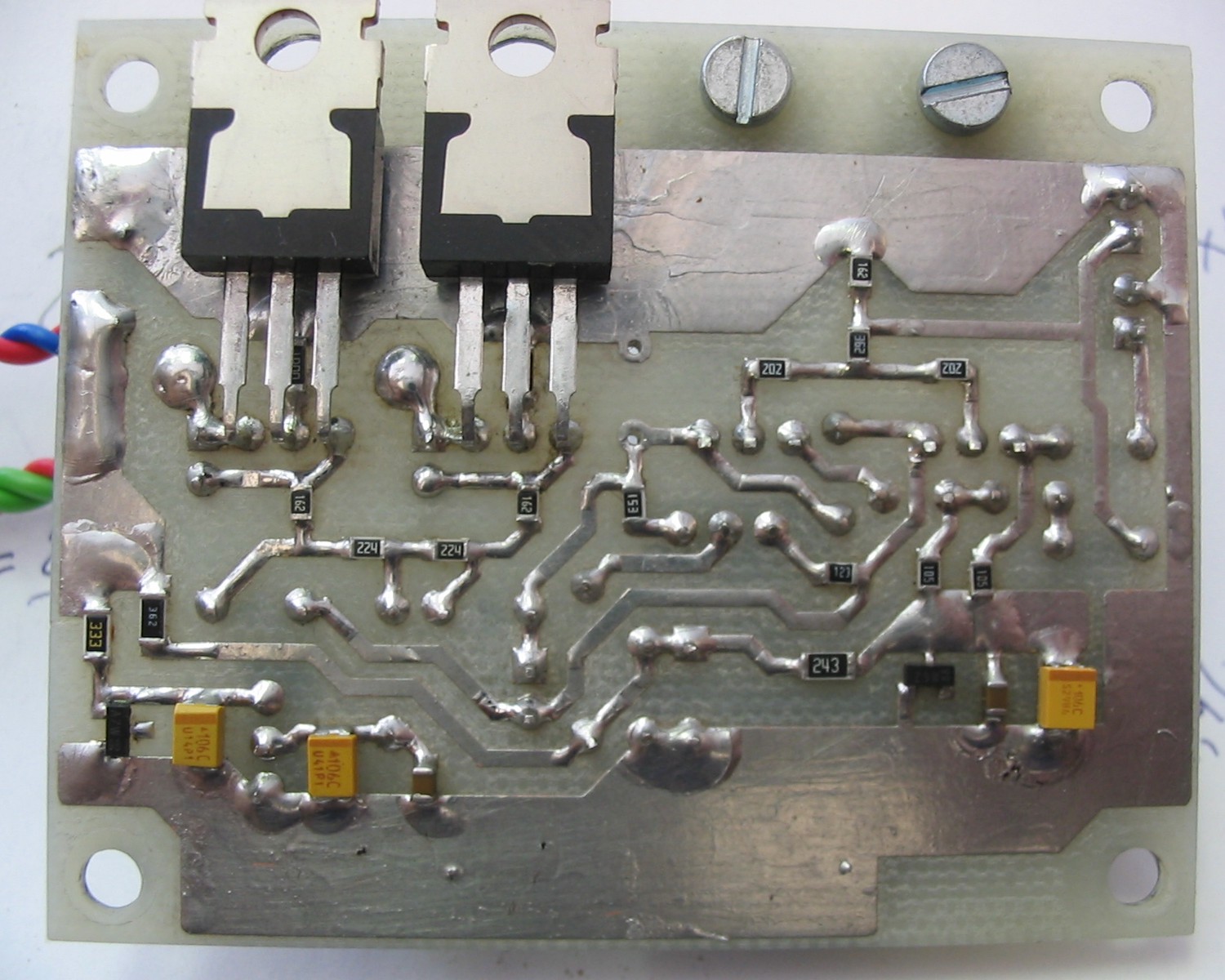
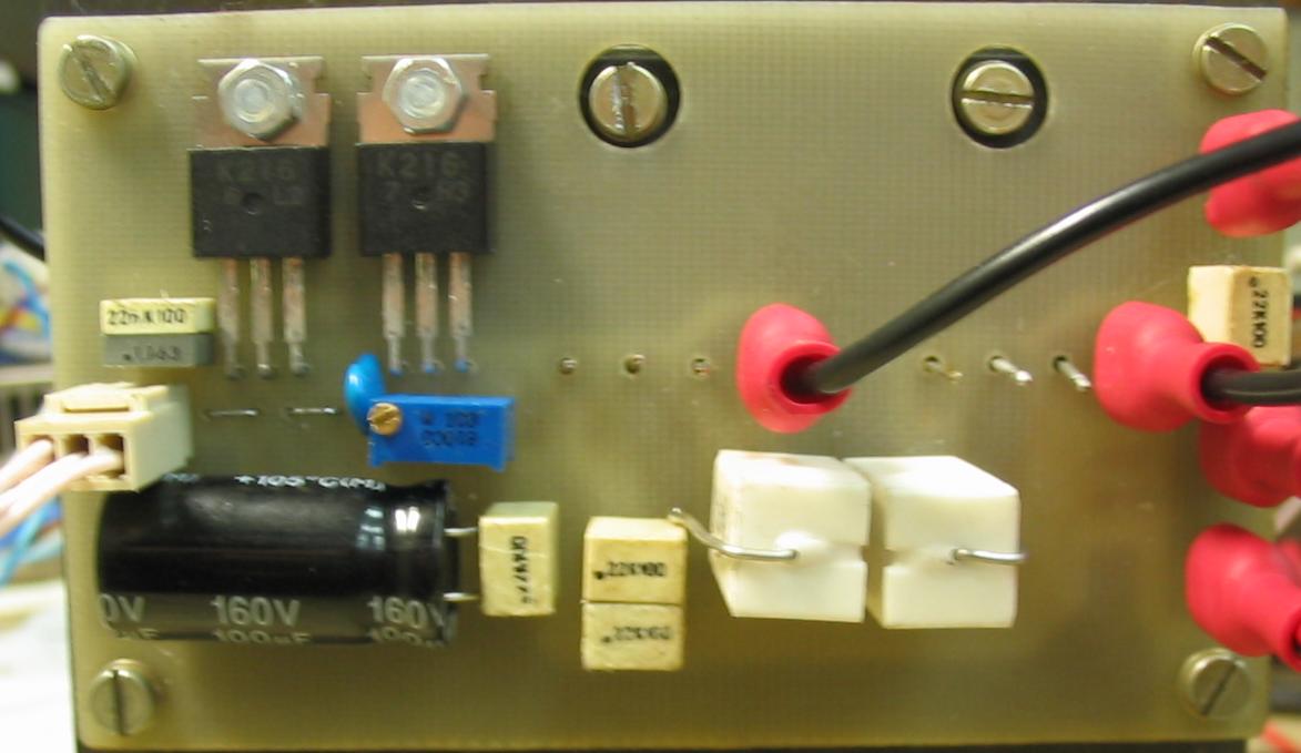
Assembled board

Comparative test with Randal RG75 (live). Recording path - Charvel Model 6, Chris Custom Screamer, ENGL Tubetoner e430, Shure SM58 (without cap), Digilab SPM-100.
Comparative test with Randal RG75 (mix).
5 W (Primary coil impedance Ra-a = 360 ohms)
Schematics (pdf)
Ready to transfer PCB (pdf)

Upper side assembly (pdf)

Bottom side assembly (pdf)

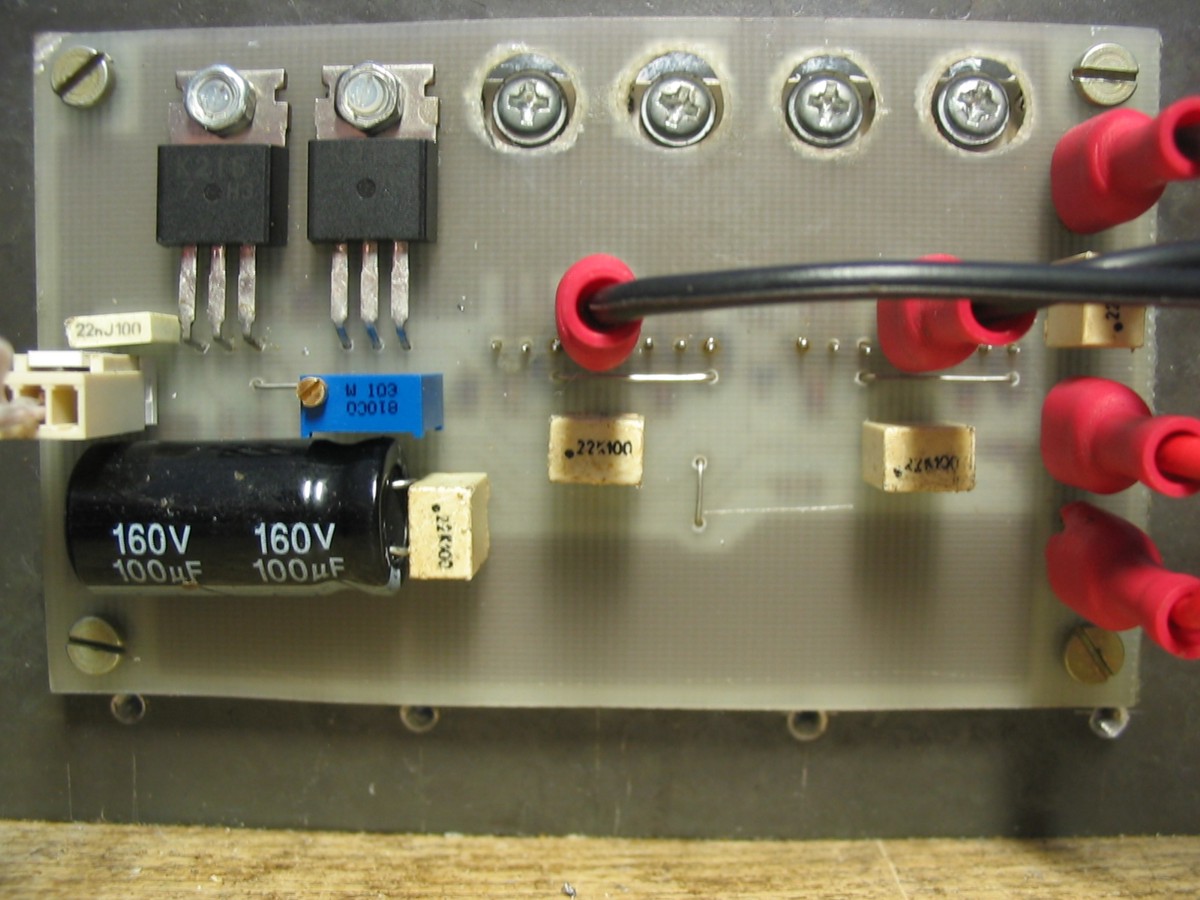
Assembled board
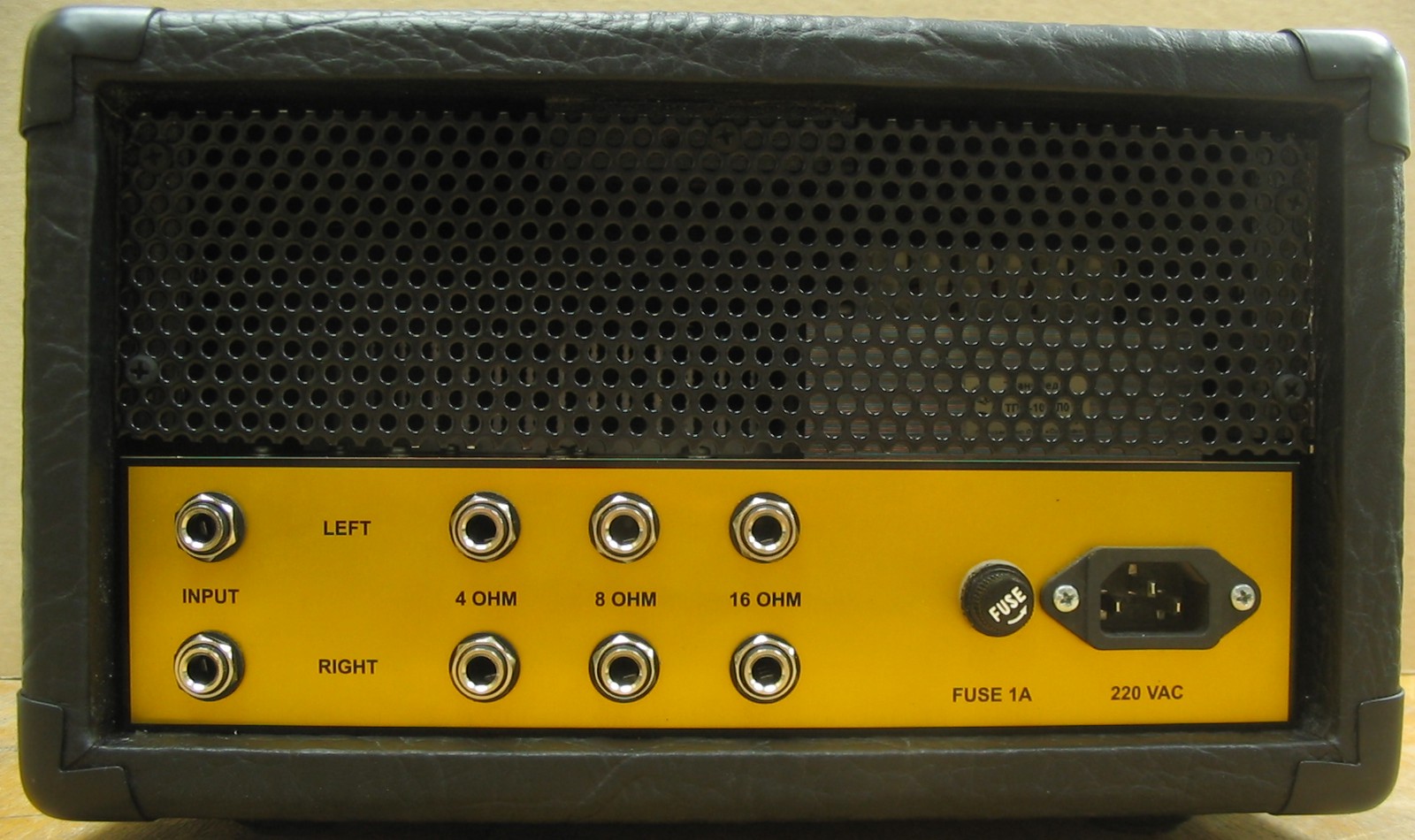
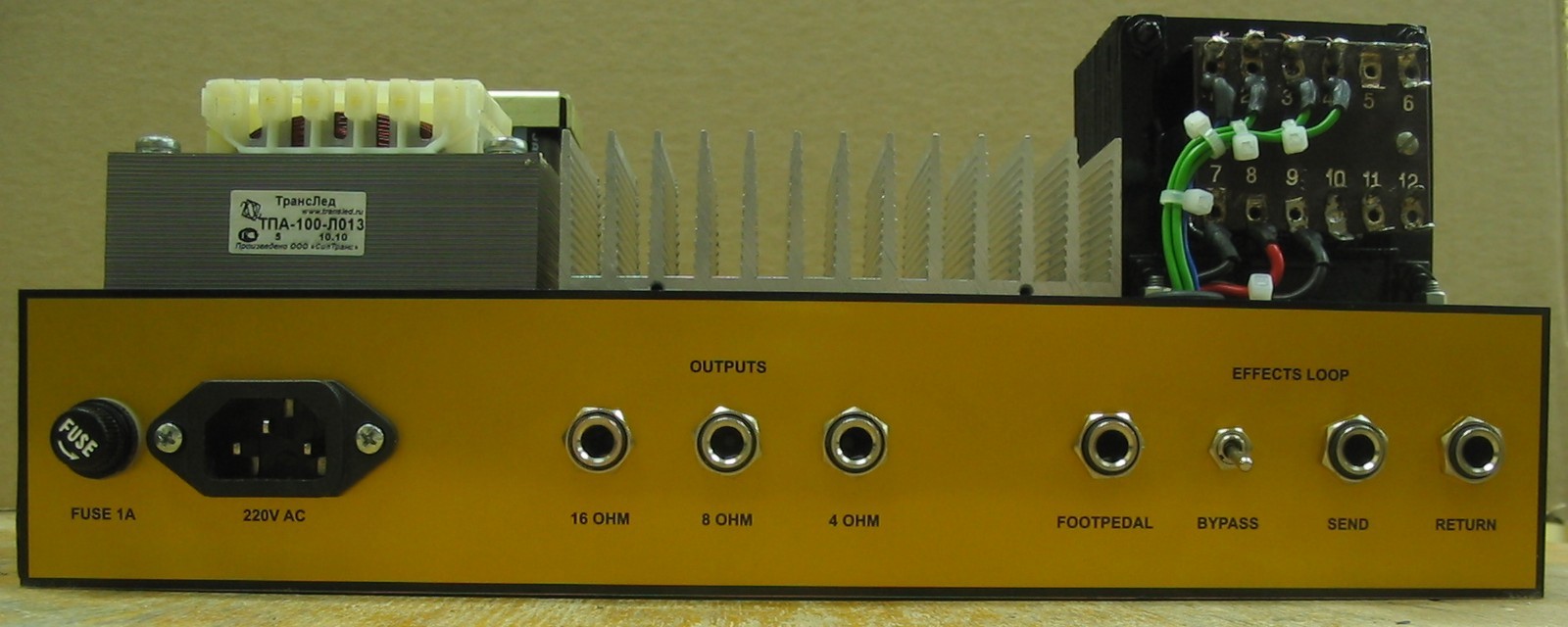
Connecting jacks and controls (pdf)

Assembled in box


Samples of PA with tube preamp UENGO-1. Recorded by dks from GtLab. Presence & Depth in mid position (PA version without Cut control).
Two samples of PA with tube preamps. Presence, Depth and Cut in clockwise position.
Recording path: Ibanez RG3120TW -> tube preamp (JCM800/SLO-100) -> fet PA -> Celestion G10 Vintage 25HR -> capacitor microphone (Octava MK105 in 2 meters from cabinet) -> mic preamp -> DELTA-44 -> Samplitude v8.
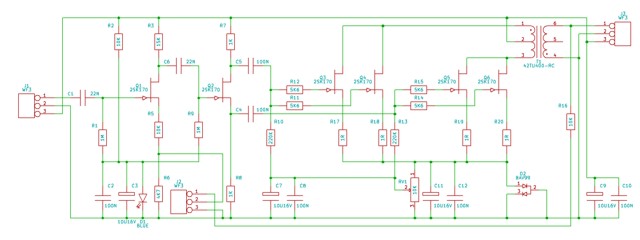
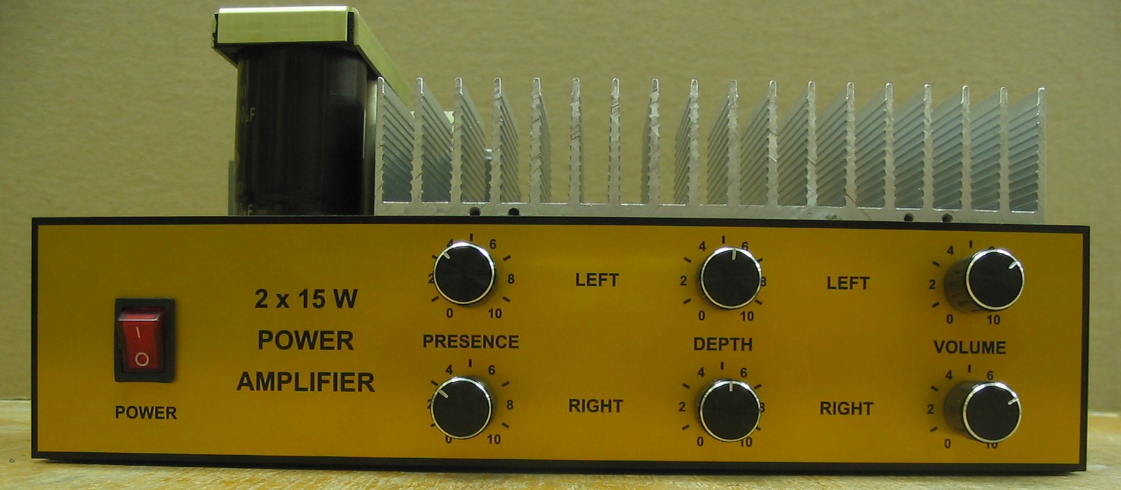
15 W (Primary coil impedance Ra-a = 600 ohms, P1,P5 supply 80V, P2-P4 output transformer connection)
Schematics (pdf)

Ready to transfer PCB (pdf)

Upper side assembly (pdf)

Bottom side assembly (pdf)

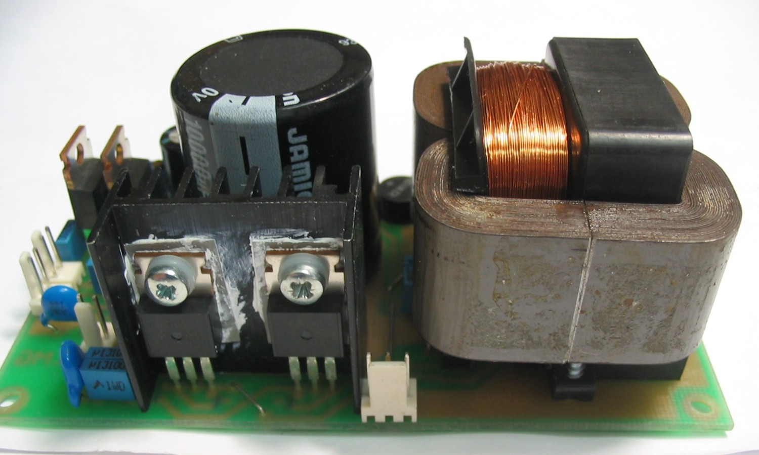
Assembled board

2x15W assembled in box


40 W (Primary coil impedance Ra-a = 200 ohms)
Schematics (pdf)

Ready to transfer PCB (pdf)

Upper side assembly (pdf)

Bottom side assembly (pdf)

Assembled board
Transformer windings for the 20x60 core:
![]()
![]()
The windings 153 (0,6 mm) - 91 (0,6 mm) - 37 (0,6 mm) - 54 (0,6 mm) - 153 (0,6 mm) - 91 (0,6 mm) - 37 (0,6 mm) -- 54 (0,6 mm) - 153 (0,6 mm) - 91 (0,6 mm) - 37 (0,6 mm) - 54 (0,6 mm) - 153 (0,6 mm). 153 - the primary, all in series. Secondary parallel. 91 - 4 ohm, 91+37 - 8 ohms, 91 +37 +54 - 16 Ohm
Mouted on chassis
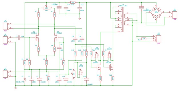
90 W (Primary coil impedance Ra-a = 80 ohms)
Schematics (pdf)

Ready to transfer PCB (pdf)

Upper side assembly (pdf)

Bottom side assembly (pdf)

Assembled board
Transformer windings for the 20x30 O-core:
![]()
![]()
Each coil 232 (0,7 mm) - 217 (1,0 mm) - 90 (0,9 mm) - 127 (0,7 mm) - 232 (0,7 mm). 232 - the primary, all in series. Secondary parallel. 217 - 4 Ohms, 217+90 - 8 ohms, 217+90+127 - 16 Ohm
Assembled in 2U rack

Some comments to the schematics:
Potentiometer "Symmetry" used to set equal amplitudes of signal halves.
Resistors R4, R7 (for 40 watts) and R5, R8 (for 90 watts) determine the sensitivity of the amplifier input. If they decrease the sensitivity increases and vice versa.
Resistor R25 (for 40 watts) and R1 (for 90 W) can be connected to the negative feedback from the output transformer with adjustable Presence. You only need to take into account that the resistance of the resistor 1,6 kOhm that is 3 times less than usual in the lamp circuits (4,7 kOhm). To get the same frequency response capacitor in series with the control you need to increase by 3 times.
Example of "Presence" and "Depth" schematics:

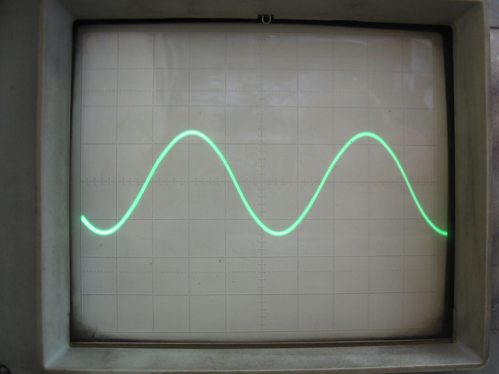
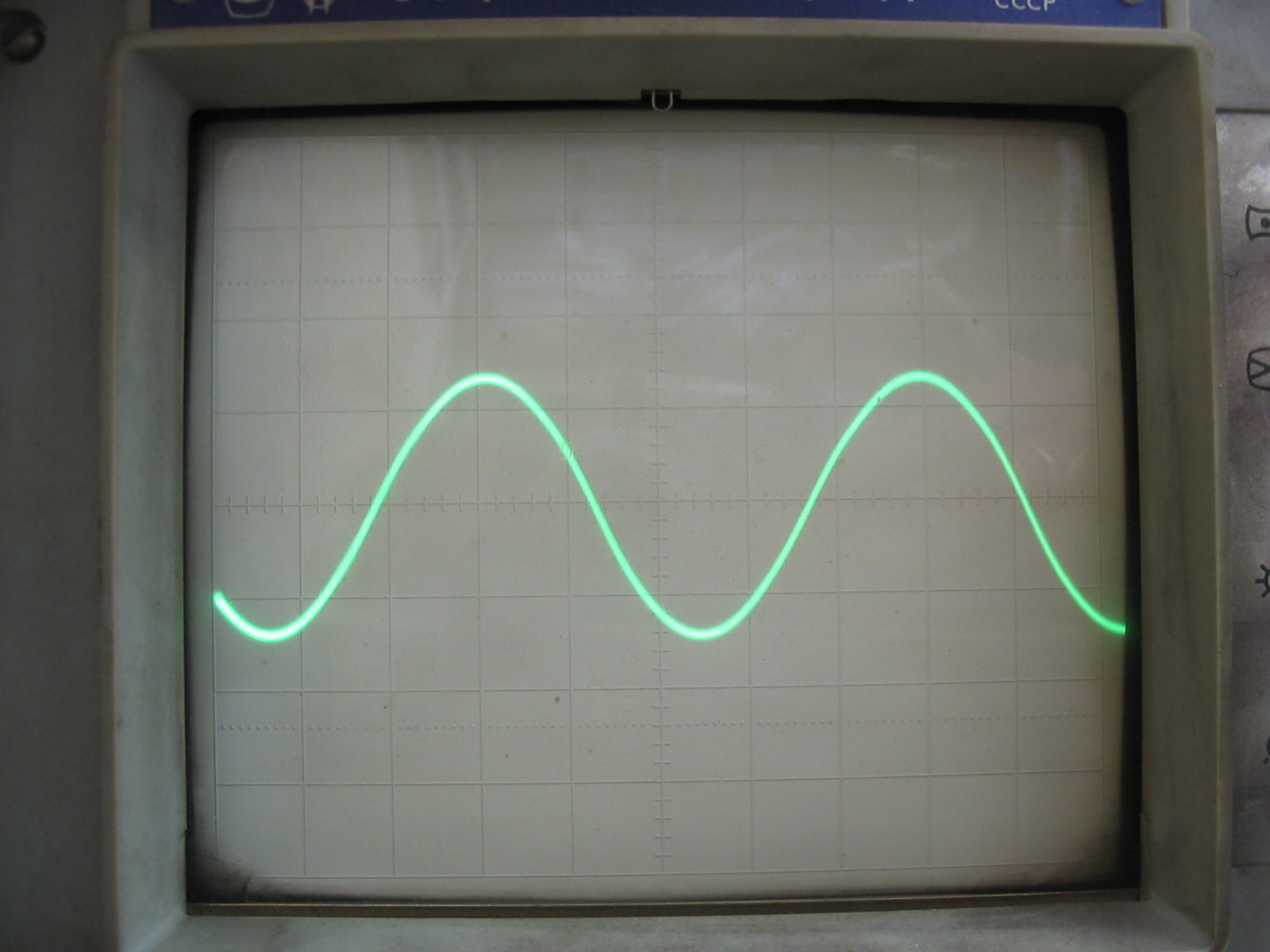
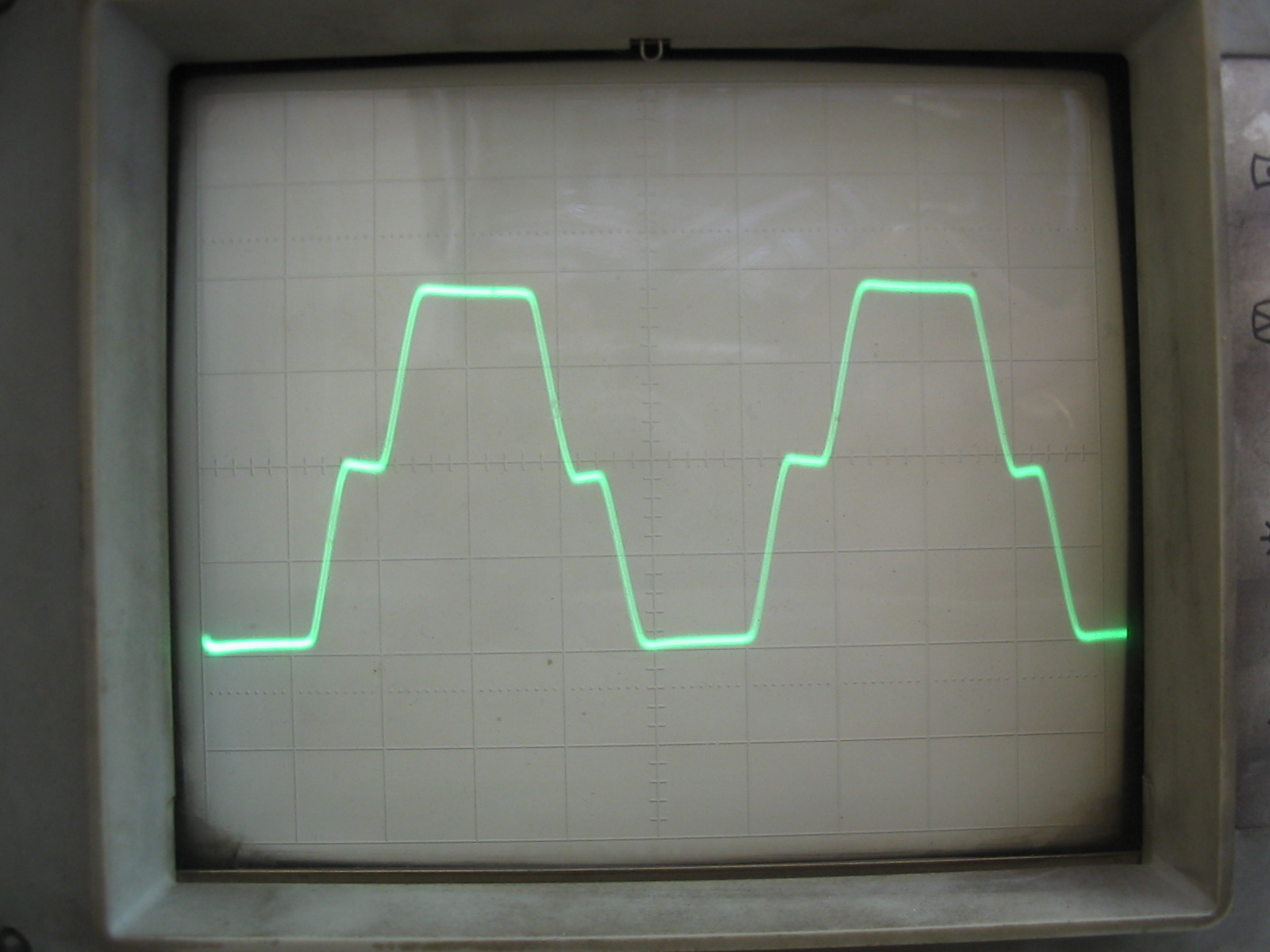
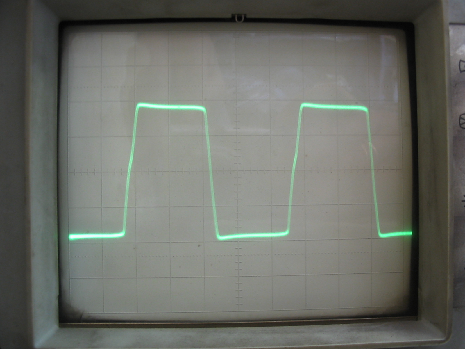
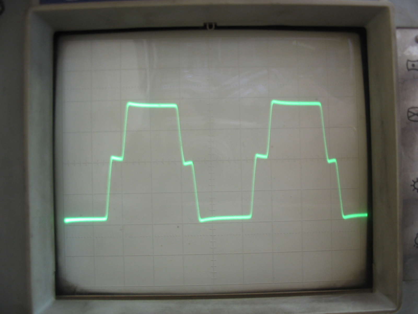
Effect of gate-drain diodes (waveforms on the right) on output signal limitation.